Call Us
+1.409.768.1419Send Us Mail
Info@RedLineIPS.comOur Location
2325 S. Main St. Vidor, TX 77662, U.S.A. Industrial Pipe Supports: Engineering Guide to Types, Functions, Loads, Movement and Selection
Download article PDF
Read offline or printPDF · 36 pages · Final version
By Hani Almufti
Engineer & Senior Manager, Cogbill Construction
Updated:
Standards listings checked:
Industrial pipe supports are engineered components and assemblies that carry piping loads, maintain the required position of a piping system, permit intended movement, and restrain movement where required by the piping design. Depending on the application, a support may carry gravity load, guide thermal expansion, resist uplift, provide axial restraint, isolate the pipe from structural steel, maintain insulation clearance, accommodate field elevation differences, or transfer dynamic and occasional loads into the supporting structure.
The term “pipe support” therefore covers much more than a piece of steel beneath a pipe. A complete support system connects the piping to the structure while controlling how forces and movement pass between them.
ANSI/MSS SP-58-2025 provides a broad industry framework for pipe hangers and supports. The governing piping code, adopted editions and project specifications still determine the requirements for a particular installation.[1]
This guide explains the principal types of industrial pipe supports, what they do, how they carry loads, how thermal movement affects them, how supports are selected and specified, and where products such as pipe shoes, adjustable supports, clamps, guides, anchors, hangers, shim blocks, slide plates, and non-welded support systems fit into an engineered piping system.
Key engineering takeaways
- Define the support’s function separately from its physical configuration.
- Select supports using the applicable loads, movement, temperature and complete structural load path.
- Specify clearances, friction and attachment details so intended movement is preserved.
- Evaluate corrosion, insulation, inspection access and project-specific fabrication requirements.
What Is a Pipe Support?
A pipe support is a component or assembly used to support, position, guide, restrain, or suspend piping and to transfer the resulting loads to a supporting structure. A useful simplified load path is:
Pipe → pipe attachment or contact interface → support assembly → structural attachment → supporting structure or foundation
That load path may be very simple. A bare pipe may rest on a support plate. It may also be considerably more complex:
Pipe → liner at the pipe contact → clamp or cradle → support member → base plate → structural attachment → supporting structure
or:
Pipe → shoe → slide plate → structural beam → pipe rack
or:
Pipe → clamp → eye nut → threaded rod → beam attachment → building steel
The configuration is different, but the engineering purpose is the same: loads generated by the piping system have to reach a structure capable of carrying them without imposing unacceptable stresses, movements, or reactions elsewhere in the system. This is why pipe supports should be considered part of the piping system and structural load path, not simply miscellaneous steel.
Support Type and Support Function Are Not the Same Thing
This distinction is fundamental. A pipe shoe describes a physical support configuration. A guide, line stop, or anchor describes what a support location is intended to do. The same basic shoe geometry might be used as a resting support, a sliding support, part of a guided support, part of a line stop, or part of an anchor assembly. Likewise, a clamp may serve as a hanger attachment, hold-down device, guide component, or part of a restraint assembly.
ISO 24200:2022 illustrates this distinction well. It separately identifies physical support types including clamped shoes, welded shoes, U-bolts, U-straps, trunnions and stanchions, while also identifying guide-support functions including guides, hold-downs, combined guide/hold-down arrangements, and line stops.[2]
An engineer therefore needs to answer two separate questions: What support configuration will be used? What movement and loads must that location permit or restrain? Confusing those questions is a common source of poor support design.
Main Functions of Industrial Pipe Supports
Most support points perform one or more of the following functions:
| Function | Movement and load behavior | Typical hardware |
|---|---|---|
| Rest or slide | Carries compression; permits specified travel; no inherent uplift capacity | Shoe, saddle, base support |
| Guide | Restrains designated transverse direction; allows axial travel | Guide angles, guide clamp |
| Hold-down | Limits uplift after the specified gap closes | Clamp or U-bolt arrangement |
| Line stop | Limits axial travel in one or both directions | Stop lug, restrained shoe |
| Anchor | Restrains specified translations and rotations; transfers forces and moments | Engineered attachment and structure |
| Suspension or spring support | Carries weight from above; spring permits designed vertical travel | Rod hanger, spring hanger |
A support can perform more than one function, but those functions should be intentional. A basic resting support, for example, should never be assumed to provide meaningful axial restraint simply because friction happens to exist between the pipe and the support.
Six degrees of freedom and real contact behavior
Define axial, transverse, and vertical axes at the support, plus rotation about each axis. A label such as guided shoe must be accompanied by its active restraint directions and clearances. A guide on a vertical riser does not automatically carry the riser weight; its axial direction is vertical.
A rest normally acts only while the pipe bears on it. Thermal movement can unload a rest, close a gap or engage a stop. These changes can redistribute reactions to neighboring supports. Where material to the design, model lift-off, friction, gaps and support flexibility rather than assuming every contact remains active.
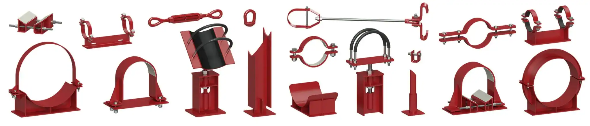
Major Types of Industrial Pipe Supports
 View full-size image
Adjustable Pipe Supports
An adjustable pipe support carries piping from below while providing a means to change the support elevation.
Adjustability is useful for:
- field fit-up;
- construction tolerances;
- sloped paving or foundations;
- equipment-nozzle alignment;
- maintaining specified pipe elevation;
- compensating for differences between design dimensions and actual field conditions.
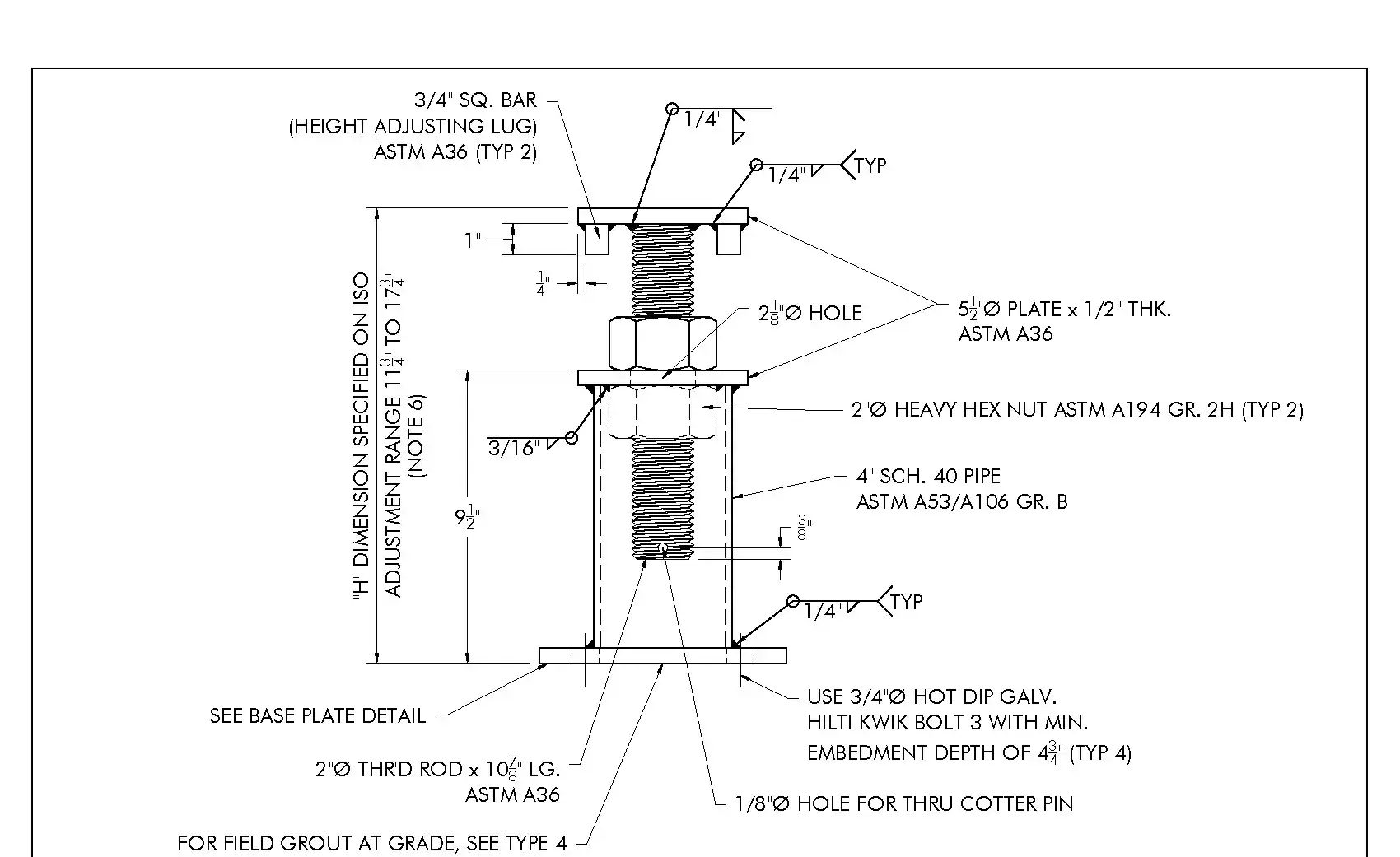
The RedLineIPS Type 1 detail identifies a non-guided adjustable base support for alignment at rotating-equipment nozzles. The illustrated Type 1 support provides ±3 inches of height adjustment (6 inches total travel), corresponding to the drawing’s installed-height range of 11¾ to 17¾ inches. Its permitted installed height, thread engagement and adjustment procedure must be established from the approved project drawing. Adjustment capability is not permission to force piping into equipment alignment or to adjust a loaded support without a defined procedure.[3]
 View full-size image
This illustrates an important point: adjustability does not eliminate engineering limits. Thread engagement, column stability, base geometry, load eccentricity, lateral loads, adjustment range, and structural anchorage still matter.
Some adjustable supports use a saddle or cradle head. Others use flat plates, U-bolts, pipe or elbow connections, valve-support heads, or specialized configurations.
Non-Adjustable and One-Time Adjustable Supports
A non-adjustable support is fabricated for a specified support elevation and is intended to remain at that geometry after installation.
RedLineIPS drawings include fixed-height structural-member base supports and field-fit configurations. A project should identify whether adjustment remains available after installation or is used only to establish the final fabricated height.
A one-time-adjustable support is different from a permanently adjustable support. It provides a way to set the final field elevation during installation and then fixes the position.
These designs are especially useful where the final support geometry should be rigid after construction.
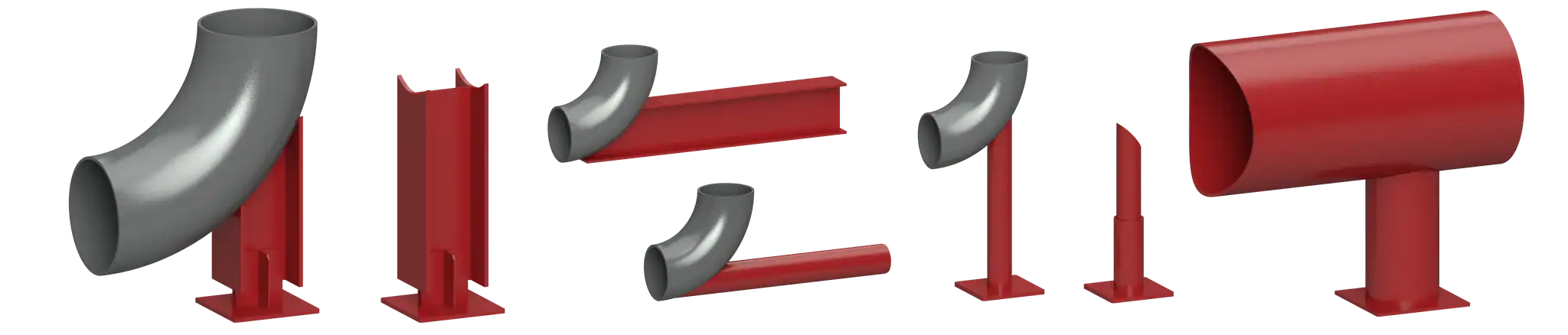
Stanchions, Trunnions, and Dummy Legs
A stanchion generally supports piping from below using a vertical structural or pipe member.
A trunnion is normally a tubular attachment connected to the pipe or fitting and used to transfer load to the supporting structure.
A dummy leg extends from a pipe spool—often from an elbow—to reach a support location where a conventional vertical support would be impractical.
 View full-size image
These supports may look simple, but the pipe attachment can be structurally significant. Local pipe stresses, wall thickness, reinforcing requirements, weld geometry, temperature, and external loads all have to be considered.
A support member being structurally adequate does not automatically mean that its attachment to the pressure-containing pipe is adequate.
Local pipe stress and load transfer
Evaluate the pipe wall and the support steel. Shoe ends, saddle edges, trunnion welds, and clamp contact can create concentrated bearing, shell bending and ovalization. Large diameter-to-thickness ratios, corrosion allowance, temperature and cyclic service can make the pipe attachment critical.[4]
A reinforcing pad changes the load path but is not a universal cure. Use a justified analytical method or appropriately verified finite-element model when simple beam assumptions do not represent the attachment. Review cyclic stress range separately from a one-time strength check.
Metallic Pipe Shoes
A pipe shoe creates a load-bearing interface between the pipe and the supporting structure.
Pipe shoes are especially common on insulated piping because they can raise the pipe above the support steel and prevent normal insulation from being crushed under the piping load.
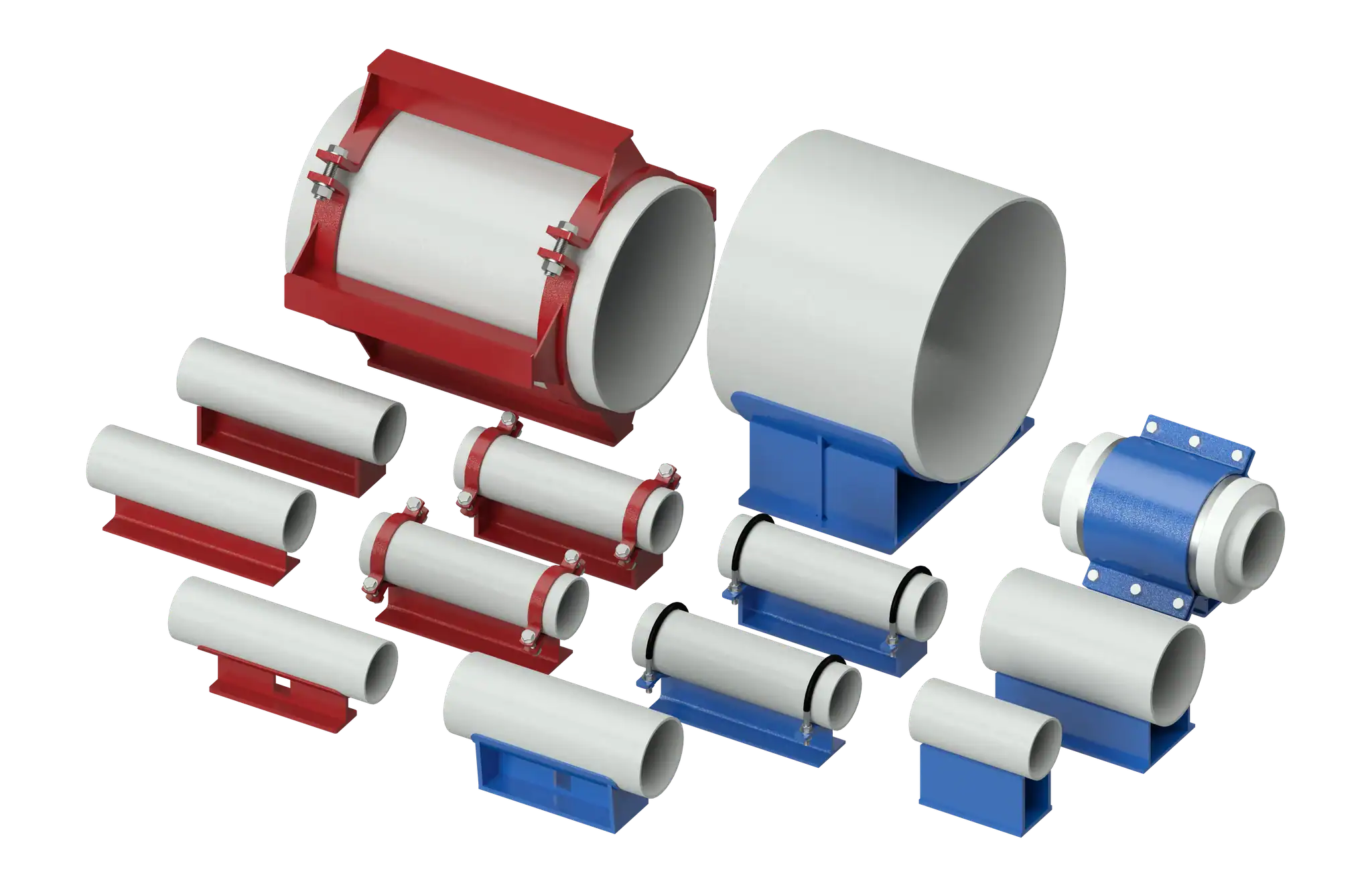
Common forms include welded T-style shoes, fabricated shoes, clamp-on shoes, saddle or cradle shoes, U-bolt-attached shoes, reinforced shoes, tall shoes, and pre-insulated cold shoes.
 View full-size image
RedLineIPS offers welded, clamp-on, cradle, and other project-specific pipe-shoe configurations. The selected drawing defines the attachment, dimensions, materials, and insulation arrangement.
Pipe shoes can also provide a defined surface for sliding and can be incorporated into guide, line-stop, or anchor arrangements.
But a pipe shoe by itself is not automatically a guide or anchor.
That function depends on the surrounding restraint details and the loads the complete assembly was designed for.
Pipe Saddles and Cradles
Saddles and cradles support the pipe over a curved surface rather than relying on a narrow point of contact.
They become particularly important for larger-diameter piping, heavy loading, insulated systems, or arrangements where broader circumferential load distribution is desirable.
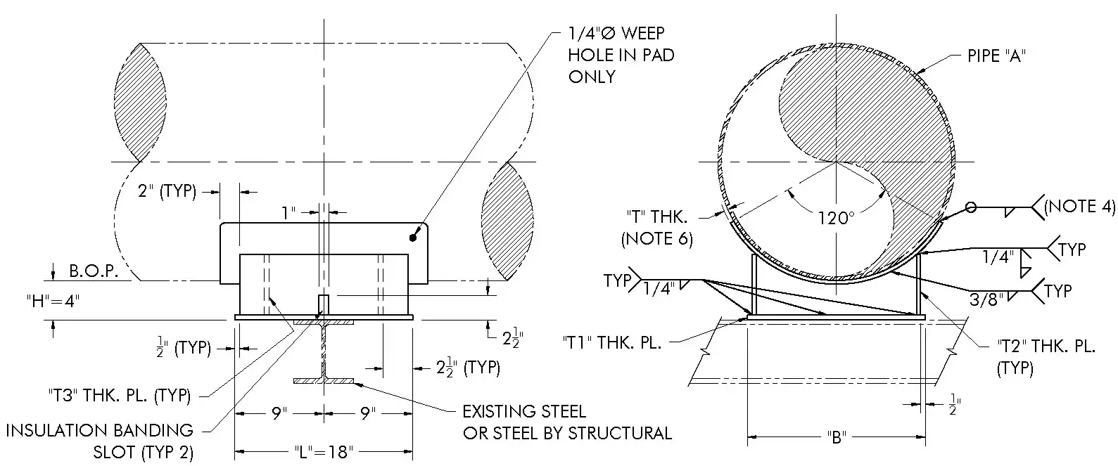
RedLineIPS Types 12A and 14A illustrate 120-degree saddle arrangements for listed pipe sizes from NPS 24 through NPS 60. These drawings demonstrate geometry options; they do not establish a universal load rating for every pipe wall, temperature, or load combination.[5]
 View full-size image
That does not mean every large-diameter pipe requires the same saddle geometry. The proper contact angle, length, plate thickness, reinforcing, pipe-wall evaluation, and support load must be determined for the specific application.
Pipe Clamps
Pipe clamps can:
- suspend a pipe;
- connect a pipe to a hanger;
- provide hold-down restraint;
- form part of a guide;
- attach a shoe mechanically;
- provide a riser support;
- connect piping to a brace or restraint.
The clamp’s behavior depends heavily on its application.
A suspension clamp carrying vertical load is not performing the same mechanical function as a clamp intended to resist uplift or transmit a large axial restraint load.
Clamp design can involve plate thickness, clamp radius, bolt diameter, bolt preload, contact width, material, liner thickness, temperature, friction, local pipe loading, and permissible slip.
This is one reason a generic instruction such as “use a pipe clamp” is insufficient for many engineered support locations.
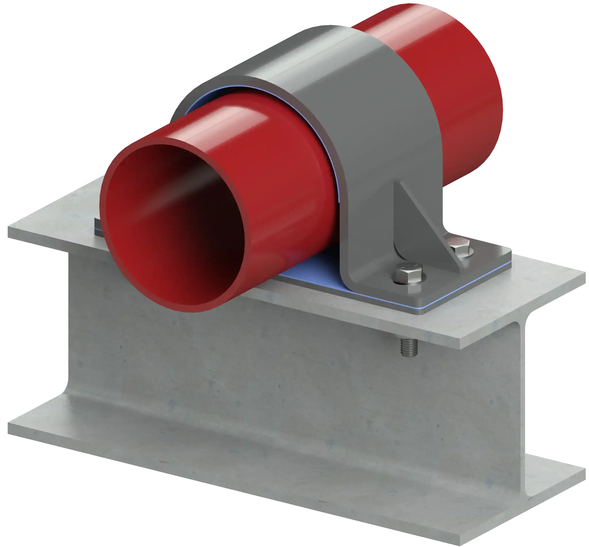
Hold-Down Clamps
A hold-down clamp typically limits upward pipe movement while permitting some combination of axial or lateral travel.
RedLineIPS standard drawings include both sliding and guided hold-down configurations with liners.
A hold-down support may be configured to:
- permit axial sliding;
- guide lateral position;
- control uplift;
- provide a predetermined clearance;
- use slotted holes to allow limited movement;
- incorporate low-friction or protective liners.
 View full-size image
The term hold-down should not be interpreted as equivalent to anchor.
An anchor is intended to transfer defined piping reactions and restrain specified degrees of freedom. A hold-down may control only vertical displacement while deliberately allowing axial movement.
U-Bolts
Depending on installation, a U-bolt may act as a loose guide, a hold-down, a clamping device, part of an adjustable support, part of a pipe shoe, or a restraint.
The torque applied to the nuts matters. Tightening a U-bolt can change it from a loose positional restraint into a frictional clamp.
Use the specified fastener grade, installation condition and tightening procedure. Excessive preload can distort the pipe or clamp; insufficient preload can permit unwanted movement. A torque value alone does not establish an axial restraint capacity.
The intended function therefore needs to be shown clearly on the support detail.
Shim Block Assemblies
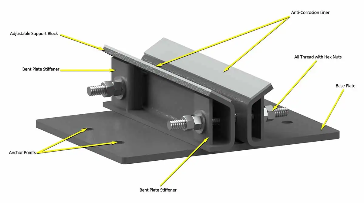
Shim blocks are used where a support needs controlled elevation, alignment, restraint geometry, or field-fit adjustment.
A shim-block assembly can be combined with:
- hold-down clamps;
- guides;
- U-bolts;
- base plates;
- sliding surfaces;
- structural beams.
The key engineering issue is not just the shim height.
The load path through the shim, contact area, material, stability, attachment, bolt geometry, pipe clearance, and movement direction all matter.
In a clamp-and-shim assembly, the shim geometry establishes the support height and restraint clearance together. Retention and bearing must remain adequate when the pipe moves or the clamp engages.
 View full-size image
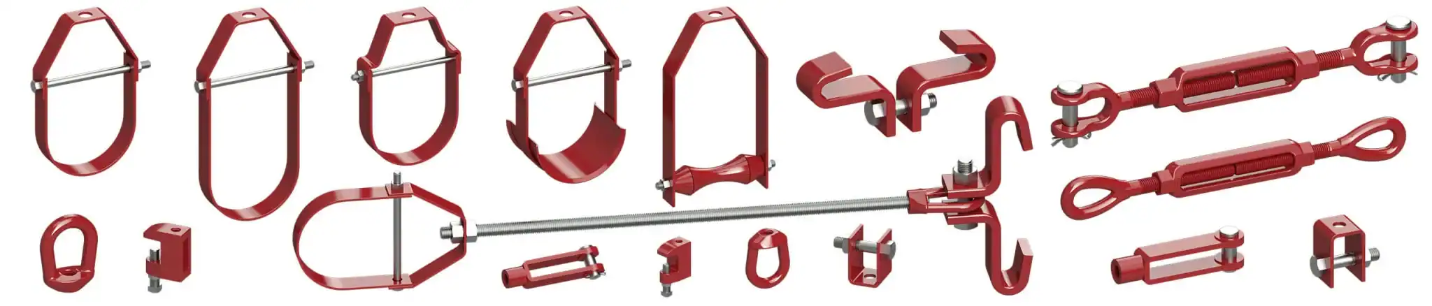
Pipe Hangers
A pipe hanger supports piping from a structure above the pipe.
A typical rigid hanger assembly can contain:
pipe clamp or clevis → eye nut or attachment → threaded rod → upper structural attachment
RedLineIPS describes its hanger assemblies in essentially this form and notes that component sizing depends on pipe size and required load.
Hanger systems can be far more complex when significant vertical thermal movement occurs. Variable spring hangers and constant-support hangers are used where a rigid hanger would transfer unacceptable loads as the pipe rises or falls with temperature.[6]
Rigid hangers, spring supports, and dynamic restraints perform different tasks. A snubber is intended to resist rapid movement while permitting slow thermal travel within its qualified operating range; it is not a substitute for a gravity support or a general-purpose damping pad.
Not every manufacturer supplies every category, but an engineer selecting supports should understand where each belongs.
 View full-size image
Guides, Line Stops, and Anchors
These components control where piping can move:
Pipe Guides
A guide normally restrains lateral movement while allowing intended movement along the pipe axis.
For example, a horizontal pipe carrying hot fluid may expand longitudinally. A properly arranged guide keeps the pipe aligned while allowing that axial travel.
RedLineIPS guide drawings specifically instruct the field to maintain clearance and ensure that the pipe shoe can slide freely within the guide.[7]
That is a good illustration of guide philosophy:
control direction without unintentionally creating an anchor.
Line Stops
A line stop restrains axial movement at a selected point.
They are used to:
- direct thermal growth;
- control movement toward expansion loops;
- distribute loads;
- protect equipment connections;
- establish piping stress behavior.
They can experience substantial axial loads and should not be created casually by welding an obstruction beside a standard shoe.
Anchors
A fully fixed anchor is commonly idealized as restraining all three translations and all three rotations. Real assemblies have finite stiffness. If a project uses the term anchor for a more limited restraint, the restrained directions, gaps, and rotational stiffness must be explicitly defined.
Depending on the design, an anchor may have to resist:
- axial force;
- lateral force;
- vertical force;
- moment;
- torsion;
- combinations of these loads.
The supporting structure has to carry the same forces that the anchor transfers out of the piping.
That sounds obvious, but it is one of the most important principles in pipe-support engineering:
A pipe restraint does not make a load disappear. It transfers that load somewhere else.
Pipe Support Loads
Pipe supports should be evaluated for the load cases relevant to the piping system rather than being selected from pipe diameter alone.
Deadweight
The basic sustained vertical load can include:
- pipe;
- fittings;
- valves;
- flanges;
- contents;
- insulation;
- cladding;
- inline instruments;
- support attachments.
Heavy valves or specialty components can create local loads much greater than those in adjacent straight pipe.[8]
Hydrostatic Test Load
Water-filled test conditions can produce greater weight than normal operation, particularly in lines that normally carry gas, vapor, or low-density fluids.
Permanent supports may therefore have to be checked for the hydrotest condition.
If temporary supports carry the test condition, document their capacity, location and removal sequence. For spring supports, define the test and travel-stop condition explicitly; shipping or travel locks must be handled according to the approved commissioning procedure.
Thermal Loads
As pipe temperature changes, the piping expands or contracts.
If guides, stops, anchors, friction, connected equipment, or structural geometry resist that movement, forces develop.
Thermal loads can be much larger than the vertical pipe weight at some restraint locations.
Friction Loads
A sliding pipe support generates resistance approximately represented by:
Fslide ≈ μkN; before slip, |Ft| ≤ μsN.
N is the compressive normal force, μk is the sliding coefficient, μs is the breakaway/static coefficient, and Ft is the tangential contact force.
The static expression is a limit, not a force that is always present. At a simple resting interface that lifts clear of its bearing, N becomes zero and that interface cannot supply sliding friction or uplift restraint.
This equation is useful, but real support friction is not perfectly constant.
Surface roughness, corrosion, contamination, temperature, bearing pressure, misalignment, start-up versus sliding friction, coatings, and wear can all change actual behavior.
For this reason, a friction coefficient should be based on the specific bearing system or engineering design basis rather than assuming that every PTFE surface, every steel surface, or every liner behaves identically.
Use supplier data for the actual bearing pair and design conditions. A low-friction coefficient taken from an unrelated PTFE product does not qualify a RedLineIPS assembly. Where friction materially affects nozzle loads or restraint reactions, assess a justified range of coefficients.
Wind and Seismic Loads
Outdoor piping, elevated piping, racks, building services, and other installations may require support design for wind or seismic action.
The load path has to continue through:
pipe → restraint → support → attachment → structure
A strong clamp attached to an inadequate beam connection is not an adequate restraint system.
Dynamic Loads
Dynamic support loads may arise from:
- reciprocating equipment;
- pressure pulsation;
- flow-induced vibration;
- acoustic excitation;
- relief-valve discharge;
- slug flow;
- water hammer;
- equipment vibration;
- seismic events.
Vibrating piping requires evaluation of dynamic response and fatigue as well as static strength. Support clearance, stiffness, and local attachment details influence that response.
PIP lists PNC00001, May 2023, for aboveground metallic piping under ASME B31.3, with a stated scope of 800°F (427°C) and below. Higher-temperature work requires a separately established design basis.[9]
Pipe Support Spacing
There is no single universal spacing table appropriate for every piping system.
Support spacing depends on factors including:
pipe diameter, wall thickness, material, fluid weight, insulation weight, temperature, allowable sag, stress, valve location, fittings, branch connections, vibration, and support function.
Do not automatically apply a spacing table for ordinary carbon-steel water piping to thin-wall stainless piping, plastic piping, large-bore process pipe, vibrating compressor piping, or heavily insulated piping.
Spacing also interacts with the entire support arrangement. Adding supports can reduce local bending but can also increase thermal restraint, friction, installation sensitivity, or load transfer into adjacent equipment.
Support layout therefore involves more than simply maximizing or minimizing the distance between supports.
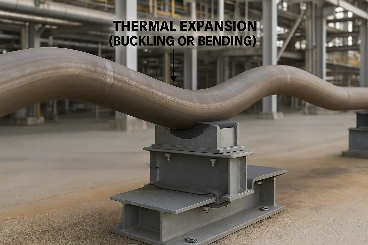
Thermal Expansion and Pipe-Support Movement
Nearly every piping system changes dimension as temperature changes.
For a straight length of pipe, thermal expansion can be estimated from:
ΔL ≈ α L ΔT
ΔL is free length change, L is initial length, ΔT is the change from installation to the evaluated temperature, and α is a suitable mean thermal-expansion coefficient over that interval.
Use consistent units. This estimates free movement, not the force in a restrained piping system. Temperature-dependent material expansion data are preferable over wide temperature intervals.
 View full-size image
The pipe-support system determines how that expansion is accommodated.
A piping system may use:
- free sliding supports;
- guides;
- line stops;
- anchors;
- expansion loops;
- expansion joints;
- spring supports;
- combinations of these.
A good support arrangement allows the piping to move where movement is intended and restrains it only where required.
One of the most damaging mistakes is unintentionally converting a sliding support into a restraint through excessive clamp preload, insufficient guide clearance, corrosion, weld placement, or a slide plate that is too short for the required travel.
Free movement is not restraint force
Illustrative calculation: a 100 ft straight run with an assumed mean coefficient of 6.5 × 10⁻⁶/°F and a 200°F rise grows approximately 1.56”. This is an assumed-material example, not a design value for every steel or a predicted nozzle displacement. Actual reactions require the piping geometry, stiffness, temperature distribution, and boundary conditions.
An untied expansion joint can introduce pressure thrust as well as spring and friction forces. Specify the joint’s effective area, movement limits and anchoring or tie arrangement; adding an expansion joint does not automatically reduce the load on every anchor.
Slide Plates and Low-Friction Bearings
Low-friction slide systems are used when reducing horizontal resistance is important.
Typical materials can include:
- PTFE;
- filled PTFE;
- graphite;
- stainless steel mating surfaces;
- engineered composite bearing materials.
Selection depends on temperature, pressure, travel, bearing load, coefficient of friction, environmental exposure, mating surface, and required service life.
A slide plate also has to be large enough to maintain full bearing throughout the design travel.
Specify axial and transverse travel, installation offset, bearing dimensions and attachment. RedLineIPS Type 8 explicitly calls for movement direction and amount on the isometric so the slide assembly can be oriented correctly.[10]
That is the correct engineering approach: movement is designed into the support, not discovered after the piping heats up.
Insulated Piping
Insulated piping creates additional support problems because normal thermal insulation is not automatically a structural bearing material.
For hot-insulated piping, shoes, saddles, shields, or engineered inserts may be used to prevent insulation crushing and maintain clearance.
For cold piping, the requirements become more demanding because the support also affects:
- vapor-barrier continuity;
- condensation;
- thermal bridging;
- moisture ingress;
- insulation compression;
- icing;
- differential thermal contraction.
A cold support may therefore be a combined structural and thermal component.
The support must carry the piping load while maintaining the required insulation performance.
Cold-service supports must preserve the load-bearing insert, insulation continuity, and vapor retarder through installation and operation. Check insert compressive stress and long-term creep at temperature. A corrosion-isolation liner is not automatically a thermal break, and not every chilled-water support is suitable for cryogenic LNG service.
This is particularly important in refrigeration, LNG, chilled-water, and data-center cooling systems.
Vibration and Pipe Supports
A support can reduce unwanted pipe movement, but a support is not automatically a vibration-control device.
Vibration can originate from:
- pumps;
- compressors;
- turbulent flow;
- control valves;
- pressure pulsation;
- two-phase flow;
- structural excitation;
- acoustic energy.
Adding stiffness may help one vibration problem and worsen another by changing the natural frequency or moving load into another location.
For vibrating piping, engineers may need to evaluate:
- support spacing;
- natural frequencies;
- dynamic stiffness;
- clamp contact;
- local pipe stress;
- fatigue;
- structural flexibility;
- support looseness;
- damping;
- restraint direction.
The solution may involve a qualified brace or dynamic restraint, changes to piping or support stiffness, damping, or correction of the excitation source. Device selection must match the response mechanism; merely adding an elastomer does not demonstrate vibration control.
“Add another support” is not a complete vibration analysis.
Pipe Support Materials
Carbon steel remains one of the most widely used materials for industrial pipe supports because of its cost, availability, strength, and fabricability.
Other common materials include:
- stainless steel;
- low-temperature carbon steel;
- chrome-moly and other alloy steels;
- aluminum for selected hanger components;
- engineered nonmetallic liners and bearing materials.
The selected material must suit the support temperature, corrosion environment, attachment method, pipe material, and project specification.
ISO 24200:2022, for example, addresses metallic offshore supports over a support design-temperature range from –46°C to 200°C and includes clamped shoes, welded shoes, U-bolts, U-straps, trunnions, stanchions, guides, hold-downs, and line stops.[11]
That temperature range belongs to that particular ISO standard and should not be treated as a universal temperature limit for all pipe supports.
Material Compatibility and Isolation Liners
A support material can be structurally suitable yet create an undesirable interface with the pipe.
Potential concerns include:
- galvanic interaction;
- coating damage;
- abrasion;
- high friction;
- vibration;
- stainless-steel contamination;
- temperature incompatibility.
Isolation liners and inserts can be used where appropriate to alter the contact interface.
RedLineIPS support configurations can incorporate materials such as PTFE, neoprene, FRP and other specified liners depending on the application. Its catalog uses liners in adjustable supports, clamps, shoes, and guide/shim-block arrangements.
A liner should not be treated as cosmetic padding.
Its thickness, compressive behavior, friction, temperature capability, chemical compatibility, creep, and retention method can influence support performance.
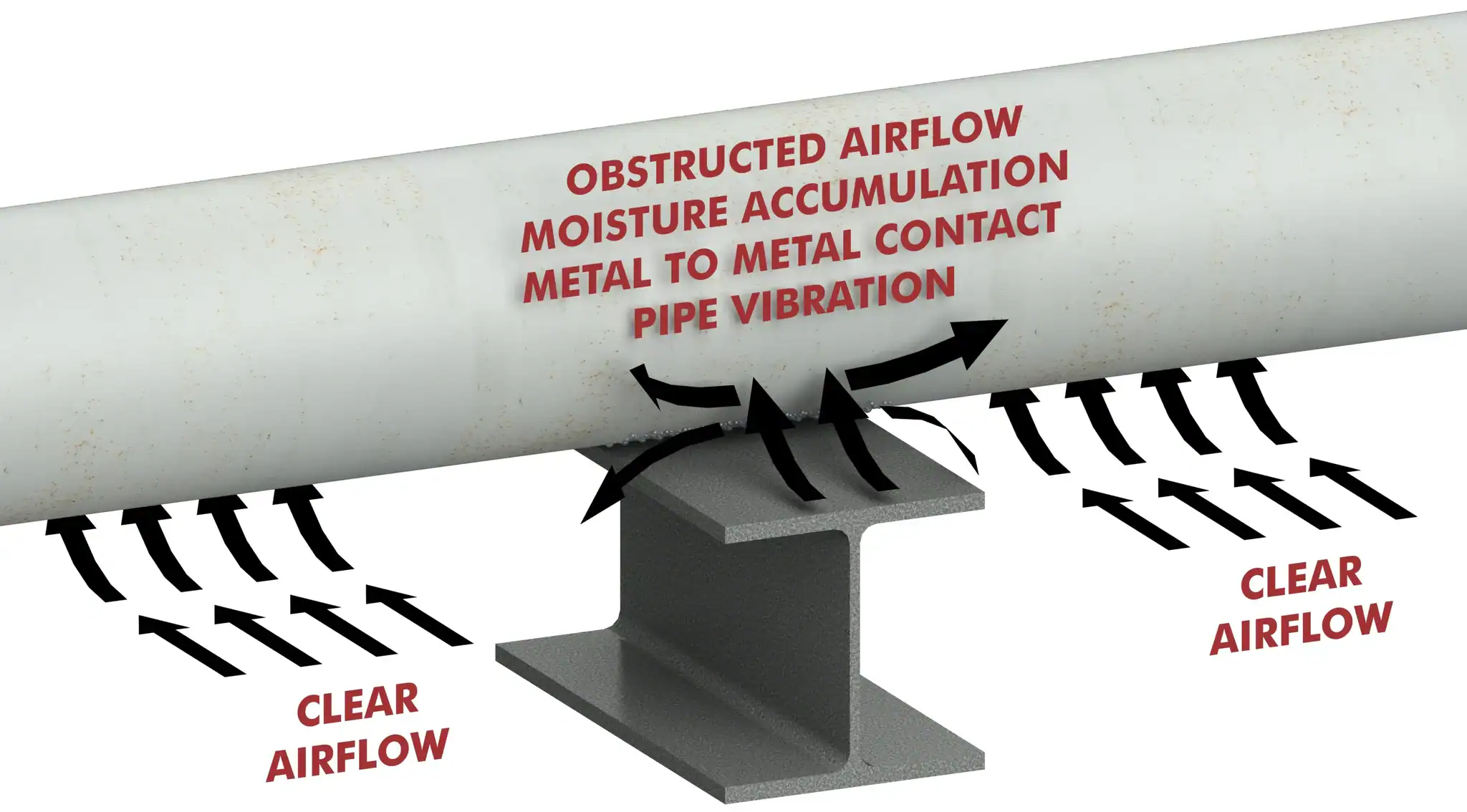
Corrosion at Pipe Supports
Pipe supports are common locations for external corrosion because they create areas where:
- coatings are damaged;
- water can collect;
- crevices remain wet;
- inspection access is restricted;
- sliding causes abrasion;
- dissimilar materials contact one another.
This degradation is commonly discussed as corrosion under pipe supports (CUPS).
AMPP’s standards-development program includes a project on risk-based management of CUPS in marine environments. This is a development project rather than an issued compliance standard.[12]
 View full-size image
A pipe shoe can remove the pressure-containing pipe wall from direct contact with a structural beam, but that does not mean the support is automatically corrosion-proof.
Potential corrosion locations then include:
- shoe-to-pipe attachment;
- clamp interface;
- weld toes;
- bolts;
- liner edges;
- shoe base;
- slide surface;
- support steel.
Effective corrosion control considers the entire support interface.
Coatings and Finishes
Common material and finish options include plain steel, shop primer, project coating systems, zinc plating, hot-dip galvanizing, and stainless-steel construction.
The correct finish depends on:
- atmosphere;
- chemical exposure;
- service temperature;
- coastal or offshore exposure;
- buried or sheltered location;
- compatibility with the pipe;
- welding sequence;
- owner specification.
Hot-dip galvanizing is widely used for support steel, but it does not remove the need to evaluate service temperature, field welding, coating repair, threaded components, or dissimilar-metal interfaces.
RedLineIPS products are commonly specified in carbon or stainless steel with galvanized, painted, or other project-required finishes depending on configuration.
Welding of Pipe Supports
There are two different welding questions in pipe-support fabrication:
Welds within the support structure and welds attaching a support to pressure-containing piping can have different governing requirements.
AWS lists D1.1/D1.1M:2025 with Amendment 1 for structural steel welding. Its scope concerns commonly used carbon and low-alloy constructional steels. Stainless structural assemblies may instead require AWS D1.6 where specified; D1.1 is not a universal welding specification for every support material.[13]
Welding directly to process piping, however, has to comply with the applicable piping code, material specification, owner requirements, welding procedure, heat treatment requirements, and examination requirements.
ASME B31.3-2024 covers the design, fabrication, assembly, erection, examination, inspection, and testing of process piping used in refineries, chemical plants, semiconductor facilities, cryogenic facilities, terminals, and similar installations.[14]
A support fabricator should therefore never assume that an attachment acceptable for ordinary structural steel can automatically be welded to any process pipe.
Bolted and Clamp-On Supports
Mechanical attachment is often selected where welding to the carrier pipe or supporting structure is undesirable.
Reasons can include:
- avoiding hot work;
- preserving pipe coatings or galvanizing;
- lined pipe;
- retrofit installation;
- modular construction;
- maintenance access;
- removal or relocation requirements;
- project restrictions on welded attachments.
But mechanical attachment does not eliminate engineering.
Clamped supports introduce other variables: bolt preload, torque, friction, slip, liner compression, clamp bending, contact pressure, temperature, and vibration.
A properly engineered clamp-on support is not merely a welded support with the weld removed.
For an axial friction clamp, use the actual contact-normal load and validated interface behavior, including liner creep, thermal changes and bolt relaxation. Bolt tension cannot simply be treated as a guaranteed axial holding force. If slip is unacceptable, specify a qualified positive load-transfer arrangement or verify the friction attachment for all applicable load cases.
The Structural Interface
Pipe-support engineering does not stop at the bottom of the support.
Base plates, anchor bolts, grout, structural beams, concrete, pipe racks, and other supporting members are part of the load path.
A base-supported system may require evaluation of:
- base-plate bending;
- concrete bearing;
- anchor tension;
- anchor shear;
- edge distance;
- grout;
- overturning;
- eccentricity;
- structural member strength;
- local beam or flange behavior.
RedLineIPS standard details show this interaction clearly. Different base supports specify different base-plate sizes, grouting requirements, adjustment limits, structural shapes, and anchor arrangements.
AISC lists ANSI/AISC 360-22 for structural steel design. Concrete anchorage requires its own applicable concrete-design provisions and anchor qualification; a structural-steel check alone does not qualify the foundation connection.[15]
The structural engineer and piping engineer therefore have overlapping responsibilities at many support locations.
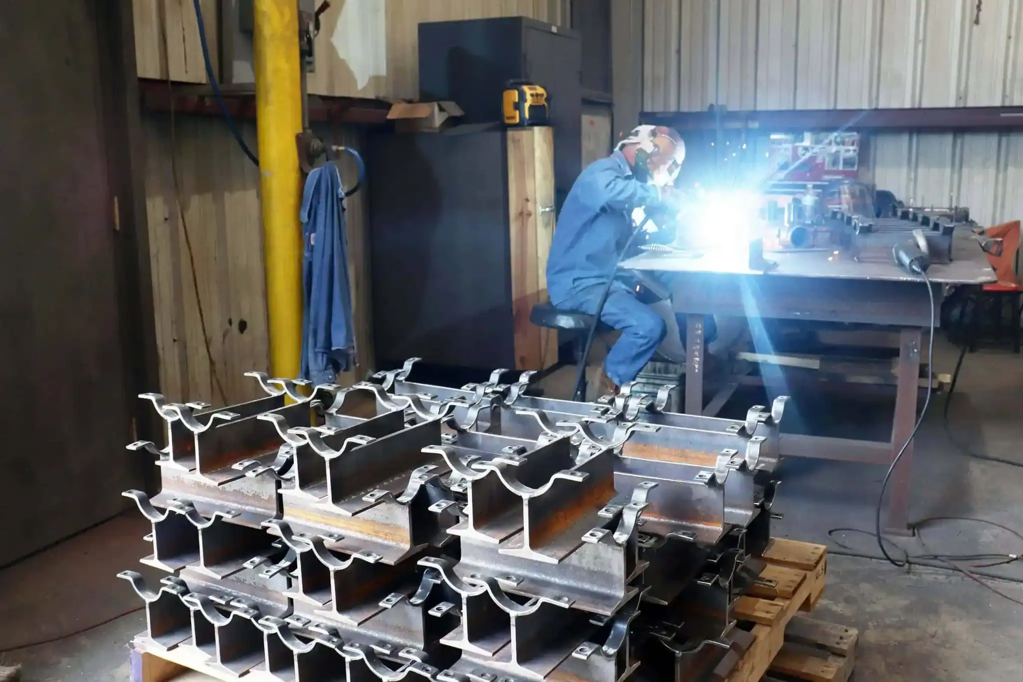
Pipe Support Fabrication
Pipe supports are often drawing-driven products.
Fabrication quality depends on much more than overall appearance.
Important characteristics can include:
- pipe-contact radius;
- support height;
- base dimensions;
- plate thickness;
- member size;
- weld size and location;
- hole size;
- slot length;
- guide clearance;
- bolt spacing;
- liner location;
- shoe length;
- slide-plate position;
- dimensional tolerance;
- flatness;
- material identification.
 View full-size image
A support that is one inch too short or a guide installed with inadequate clearance can alter the piping system even if the weld quality is excellent.
This is why dimensional inspection matters as much as fabrication workmanship.
Installation and Field Conditions
Many support problems originate during installation rather than design.
Common issues include:
- support installed at incorrect elevation;
- cold setting not established;
- slide plate centered when it should be offset;
- guide clearance too small;
- clamp over-tightened;
- missing liner;
- damaged coating;
- support welded to the wrong structural location;
- temporary support left in service;
- support loaded before grout cures;
- pipe resting on insulation instead of the intended load-bearing member;
- field modifications made without engineering review.
A good support detail should communicate the installation condition clearly enough that the intended behavior survives construction.
Inspection and Quality Control
The extent of inspection depends on service and project requirements, but industrial support QA may include verification of:
- material grade;
- material traceability;
- dimensions;
- weld size;
- weld quality;
- bolt and fastener type;
- NDE where specified;
- coating preparation;
- coating thickness;
- galvanizing;
- liner installation;
- slide-plate bonding;
- support identification;
- tag numbers;
- documentation.
For engineered or custom supports, inspection should be against the approved fabrication drawing rather than against a generic catalog image.
In-service inspection and support replacement
Inspect for loss of bearing, unexpected lift-off, seized slides, missing gaps, loose fasteners, cracked welds, coating damage, corrosion and insulation wetting. Compare cold and operating positions where practicable. An unloaded-looking support is not proof that removal is safe under every operating condition.
Before removal or replacement, establish temporary load transfer and verify piping stability and adjacent equipment loads. Record field changes and update the support drawing and analysis when geometry, stiffness, friction or restraint function changes.
Applicable Pipe-Support Standards and Codes
Establish the code boundary and the editions adopted by the project and jurisdiction before design. A newer publisher edition does not automatically replace the contracted edition. The following edition and scope listings were checked on September 14, 2026. Consult the complete governing standards for detailed requirements.
Several standards commonly interact.
ANSI/MSS SP-58-2025
Pipe Hangers and Supports — Materials, Design, Manufacture, Selection, Application, and Installation
Broad framework for hanger and support materials, design, manufacture, selection, application and installation. Apply the edition specified for the project.[16]
PIP PNC00001 — May 2023
Pipe Support Criteria for ASME B31.3 Metallic Piping.
Design and selection criteria for aboveground ASME B31.3 metallic piping, limited by the published scope to 800°F (427°C) and below.[17]
ASME B31.3-2024
Process Piping. Relevant to many refinery, chemical, terminal, semiconductor, cryogenic, and process-industry piping systems.[18]
ASME B31.1-2024
Power Piping
Used for piping in power generation and certain industrial, institutional, geothermal, and central heating/cooling systems.[19]
ASME B31.9-2025
Building Services Piping
Applicable to many building-services piping systems within buildings and property limits. The applicable code for a particular chilled-water, utility, or data-center piping system must be established by the project and jurisdiction.[20]
ISO 24200:2022
Provides support design requirements for specified metallic offshore topside applications and includes welded shoes, clamped shoes, U-bolts, U-straps, trunnions, stanchions, guides, hold-downs, and line stops.[21]
AWS D1.1/D1.1M:2025-AMD1
Structural welding requirements for applicable carbon and low-alloy steel support construction where invoked by the design basis. Confirm applicable amendments, errata, material scope and project requirements.
ANSI/AISC 360-22
Provides the principal structural-steel design framework where pipe-support loads are transferred into structural members governed by AISC requirements.
ASME BPVC Section IX, 2025, addresses welding, brazing and fusing qualifications. It does not supply the complete design and production acceptance rules for a support attachment. Owner, EPC, insulation, coating, seismic and structural specifications may add requirements.[22]
How to Select an Industrial Pipe Support
A practical selection sequence starts with the piping system, not the support catalog.
1. Establish the support function
Determine whether the point is intended to rest, slide, guide, hold down, stop, anchor, suspend, or dynamically restrain the pipe.
2. Determine the loads
Identify signed forces and moments for relevant installation, empty, operating, shutdown, test and occasional conditions. State coordinate axes and whether reactions are factored or unfactored; retain concurrent load combinations rather than combining unrelated maxima without explanation.
3. Determine pipe movement
Establish expected displacement from cold to operating condition and any occasional displacement.
4. Determine pipe and insulation geometry
The support must accommodate actual OD, insulation thickness, jacketing, fittings, flanges, and nearby interferences.
5. Determine attachment restrictions
Establish whether welding to the pipe or structure is allowed.
6. Select the support family
This may point toward a shoe, clamp-on shoe, adjustable base support, stanchion, saddle, hanger, hold-down clamp, shim-block assembly, guide, anchor, or another design.
7. Select the bearing and contact interface
Determine whether bare metal contact, protective liner, FRP, elastomer, PTFE, graphite, or a purpose-designed cold-support insert is required.
8. Verify structural capacity and load path
Check the pipe wall and local attachment, support assembly, welds, bolts, bearings, supporting steel and concrete anchorage. Confirm that the stiffness, gaps and contact behavior match the piping analysis.
9. Address corrosion and environmental exposure
Choose appropriate materials, coatings, drainage, isolation, and inspection access.
10. Define fabrication and installation requirements
The drawing should identify the dimensions and information required to reproduce the design correctly.
This process prevents a common error: choosing a support because its photograph resembles the required arrangement.
What Information Does a Pipe-Support Manufacturer Need?
For custom industrial support fabrication, useful purchasing information normally includes:
- support type or drawing;
- support tag;
- pipe NPS and actual OD when necessary;
- pipe material;
- pipe wall or schedule where attachment design requires it;
- operating and design temperature;
- insulation thickness;
- required support height or bottom-of-pipe elevation;
- vertical load;
- axial and lateral loads when applicable;
- uplift load;
- expected movement and direction;
- guide or restraint requirements;
- shoe or base length;
- base-plate dimensions;
- bolt-hole or slot arrangement;
- material grade;
- coating or finish;
- liner or isolation material;
- slide-plate requirement;
- welding specification;
- inspection/NDE requirements;
- documentation requirements;
- quantity.
A fabricator cannot determine every required design load from pipe size alone.
This is why published dimensions and load ratings, where available, apply only to the configuration and conditions for which they were developed.
Standard Pipe Supports vs. Custom Pipe Supports
Industrial projects usually contain both.
Standardized details are effective when many supports share:
- pipe sizes;
- service conditions;
- elevations;
- structural interfaces;
- load ranges;
- movement requirements.
Custom supports become necessary when there are unusual:
- loads;
- pipe sizes;
- elevations;
- clearances;
- materials;
- insulation systems;
- field conditions;
- movement requirements;
- retrofit constraints;
- equipment connections.
Standard details can be efficient when their assumptions match the service. Unusual loads, movement or interfaces require a reviewed modification or a custom support rather than extrapolation from a similar-looking catalog figure.
Industrial Applications
Pipe supports are required wherever piping has to remain safely positioned while carrying its own loads and responding to operating conditions.
Typical industries include:
- refining;
- petrochemical and chemical processing;
- oil and gas;
- LNG;
- terminals;
- power generation;
- offshore platforms;
- pharmaceutical and semiconductor facilities;
- water and wastewater;
- industrial utilities;
- chilled-water systems;
- district cooling;
- data centers and liquid-cooling infrastructure.
The engineering emphasis changes by application.
A refinery may place particular emphasis on high temperature, chemical exposure, vibration, and process-code requirements.
An offshore installation may emphasize corrosion, dynamic loads, compact geometry, and maintainability.
Data-center cooling projects may emphasize prefabricated modules, field fit-up, insulation integrity, condensation control, vibration and minimizing field hot work. Clamp-on shoes, adjustable supports, guides, line stops and hangers serve different functions. Below-ambient service requires a designed insulation and vapor-retarder detail; warm-water loops must be assessed against their actual temperatures and ambient dew point.
The support must be selected for the system—not merely for the nominal pipe diameter.
RedLineIPS Industrial Pipe Supports
RedLineIPS is a brand of piping products manufactured by Cogbill Construction (opens in a new tab) ↗ in Vidor, Texas. Its range includes custom metallic and nonmetallic piping products for industrial systems.
The RedLineIPS metallic support range includes:
adjustable pipe supports, non-adjustable supports, base supports, dummy legs, pipe shoes and saddles, hold-down clamps, shim-block assemblies, hangers, guides and stops, and related custom support configurations.
Fabrication requirements should be defined through approved drawings, material and coating specifications, and the documented scope of supply.
The company’s standard drawing library also shows an important characteristic of industrial support fabrication: a single product family frequently requires multiple configurations. The RedLine drawings include field-adjustable, one-time-adjustable and non-adjustable supports, small-bore and large-bore designs, multiple guide arrangements, pipe shoes, saddles, hold-down clamps, support blocks, slide interfaces, and other support details.
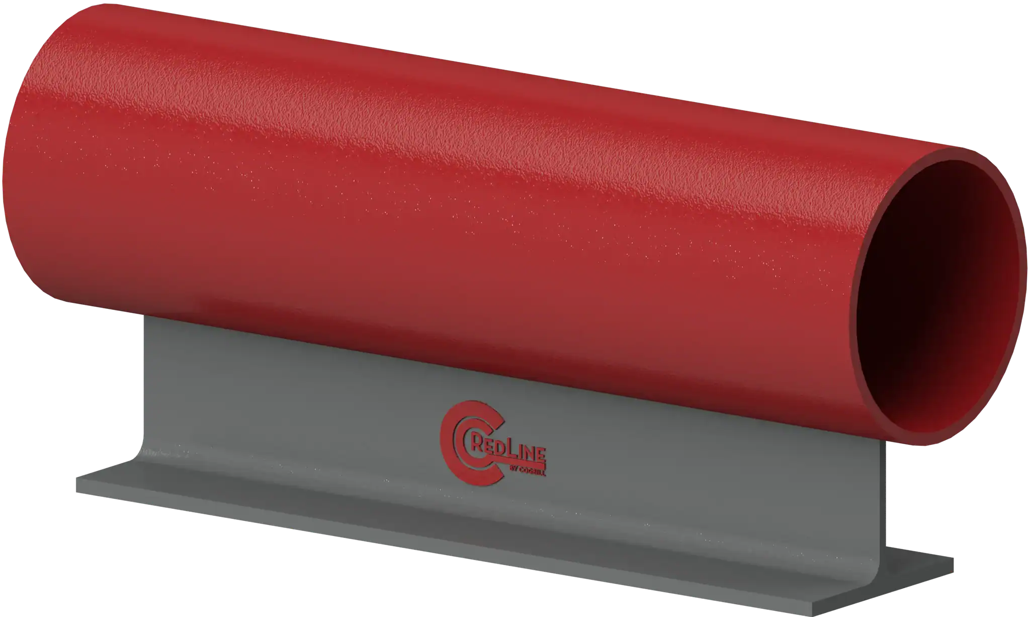 View full-size image
For project work, RedLineIPS can fabricate from customer support drawings or from the dimensional and material information required for the selected support type.
For custom supports, assign responsibility for piping reactions, local pipe checks, support calculations and structural connections. RedLineIPS dimensional drawings or order forms do not by themselves constitute an engineered capacity rating.
For a project quotation, provide the support schedule, pipe size and wall, material, temperature, insulation, required height, loads and travel, attachment restrictions, finish, quantity and documentation requirements. Explore RedLineIPS metallic piping supports and identify the applicable product drawing or order form.
Request a pipe-support quotation with your project drawings and requirements.
Frequently Asked Questions About Industrial Pipe Supports
What is an industrial pipe support?
An industrial pipe support is an engineered component or assembly that carries piping loads, positions the pipe, permits required movement, or restrains movement and transfers those forces into a supporting structure.
What are the main types of pipe supports?
Common types include pipe shoes, saddles, adjustable supports, stanchions, trunnions, dummy legs, clamps, hold-down clamps, U-bolts, hangers, guides, line stops, anchors, spring supports, slide assemblies, and insulated cold supports.
What is the difference between a support and a restraint?
A support primarily carries load, usually vertical load. A restraint intentionally limits movement in one or more directions.
Some assemblies perform both functions.
What is the difference between a guide and an anchor?
A guide normally permits axial pipe movement while limiting lateral movement.
A fully fixed anchor restrains three translations and three rotations in an idealized model. The actual restraint directions, flexibility and load capacity must be defined for the installed assembly.
What is a line stop?
A line stop is a restraint designed primarily to limit axial pipe movement at a selected support location.
Why are adjustable pipe supports used?
Adjustable supports allow the final pipe elevation to be established or corrected during installation and can compensate for construction tolerance, sloped foundations, equipment alignment, or changing field conditions.
Why are pipe shoes used?
Pipe shoes transfer pipe loads to supporting structures while providing clearance, a defined bearing surface, or a sliding interface. They are particularly common on insulated piping.
What is a clamp-on pipe shoe?
A clamp-on shoe attaches mechanically to the pipe rather than using a welded pipe attachment. It may be selected where welding is restricted, undesirable, or unnecessary.
What is a hold-down pipe clamp?
A hold-down clamp limits uplift or vertical movement. Depending on the design, it may still allow axial sliding or controlled lateral movement.
What is a pipe support shim block?
A shim block provides controlled elevation or spacing beneath a support or clamp assembly. Engineered shim-block systems can also form part of guided, sliding, or hold-down supports.
How much weight can a pipe support carry?
There is no universal answer based solely on pipe size.
Capacity depends on support geometry, materials, welds, bolts, temperature, load direction, pipe attachment, structural support, and applicable design criteria. Manufacturer load ratings apply only to the conditions for which they were established.
How far apart should pipe supports be?
Support spacing depends on pipe diameter, material, wall thickness, fluid weight, insulation, temperature, allowable sag, stress, vibration, and concentrated loads. A generic spacing table should not be used without confirming that its assumptions match the piping system.
Do pipe supports have to allow thermal expansion?
Where thermal movement is expected, the support system must accommodate or intentionally restrain that movement according to the piping design. Sliding supports, guides, anchors, line stops, spring supports, and expansion loops may all play a role.
Can pipe supports cause corrosion?
Yes. Support interfaces can damage coatings, retain moisture, create crevices, or restrict inspection. Corrosion under pipe supports is a recognized integrity problem, particularly in wet, coastal, chemical, and marine environments.
What materials are used for industrial pipe supports?
Carbon steel is common. Stainless steel, low-temperature carbon steel, alloy steel, and engineered nonmetallic liners or bearing materials are also used depending on temperature, corrosion, pipe material, and project requirements.
Can pipe supports be galvanized?
Many carbon-steel supports are hot-dip galvanized, but coating selection must consider temperature, welding, project requirements, hardware, and the environment.
What pipe supports are used for insulated piping?
Common solutions include pipe shoes, saddles, insulation shields, load-bearing inserts, hangers with insulation protection systems, and cold shoes or pre-insulated supports.
What supports are used for chilled-water piping?
The appropriate system depends on the project, but chilled-water supports commonly require consideration of pipe weight, insulation compression, vapor-barrier continuity, condensation, thermal movement, corrosion, vibration, and cold bridging.
Where can I buy custom industrial pipe supports?
Custom industrial pipe supports are normally purchased from specialized pipe-support manufacturers or qualified fabrication shops that can work from project drawings and provide the required materials, welding, coatings, dimensional control, and documentation.
Cogbill Construction, in Vidor, Texas, manufactures custom industrial pipe supports under the RedLineIPS brand, including adjustable and non-adjustable supports, pipe shoes and saddles, clamps, shim-block assemblies, guides, stops, hangers, and related fabricated piping products.
The Engineering Role of Pipe Supports
Pipe supports are often inexpensive compared with the piping, equipment, and structures around them, but their effect on the system can be substantial.
A properly designed support system has to do several things at once: carry the piping safely, preserve alignment, allow intended thermal movement, provide required restraint, protect insulation and pipe surfaces, transfer forces into the structure, tolerate the environment, and remain practical to fabricate, install, inspect, and maintain.
That is why pipe-support engineering begins with loads and movement, not with a catalog figure number.
The support geometry comes afterward.
A shoe, clamp, stanchion, hanger, shim block, guide, or anchor is successful only when it performs its intended function within the complete piping system.
This guide introduces adjustable and non-adjustable supports, metallic pipe shoes, clamps and hold-downs, guides and anchors, shim-block assemblies, hangers, ClamBrace, sliding interfaces, and pipe supports for AI data centers.
Sources
3, 5, 7, 10. RedLineIPS Drawings.pdf. User-supplied drawing collection: PDF p. 5 Type 1; pp. 9 and 12 Types 12A and 14A; p. 20 Type 20; pp. 37–38 Types 7S and 8. Configuration examples only; use approved project drawings for fabrication.
6. Process Industry Practices. PIP PNC00001.pdf, June 2002, printed pp. 3–9, sections 4–6. User-supplied legacy edition used for established principles of friction, attachments, vibration, hydrotest and spring supports; not represented as the 2023 text.
About Hani Almufti
Hani Almufti is an Engineer & Senior Manager at Cogbill Construction (RedLineIPS). He is responsible for product strategy, materials selection and technical guidance for the RedLineIPS line of metallic and non-metallic pipe supports and accessories.
As an industrial engineer with 15 years in pipe supports and 10 years in offshore energy corrosion, he specializes in corrosion under pipe supports (CUPS) and the performance of FRP and other non-metallic and metallic supports. His expertise spans corrosion mitigation, reliability engineering and process improvement to reduce risk, noise/vibration and lifecycle costs across onshore and offshore assets.
x